Force Glove
5/14/2023
A Project By Jonas Funk (jwf224) & Antti Meriluoto (ahm234).
Demonstration Video
Introduction
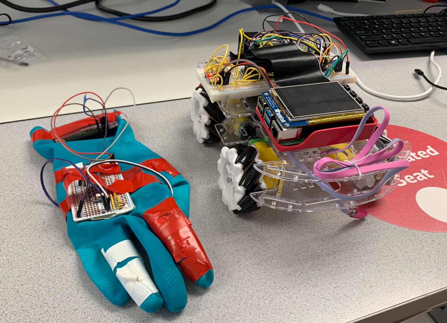
Force Glove is a wearable product that controls a tiny wireless omni-directional robot. The glove controls the movement of the robot in two separate ways. (1) Rotating the robot and (2) "throwing" the robot either forward, backwards, left,or right. To make this possible, the glove consists of two flex sensors that determine when there is a "grab" of the fist, an IMU to get the direction of the rotation and throw, and a Raspberry Pi Zero to send the data to the robot (controlled by the Pi 4) via bluetooth. The robot itself consisted of the Pi 4, two motor controllers, two power supplies, and four omni-directional wheels. These wheels made it possible to throw the robot in any direction without needing to rotate beforehand.
Project Objective:
In todays age, being able to wirelessly control robots has some really neat applications. Some wirelessly controlled robots, such as the ones at DAWN Avatar Robot Cafe, in Japan, give paralyzed people an opportunity to still earn income as waiters [1]. Our objective is to respond to a variety of hand movements with robot movement. This includes detecting grabs, hand rotations, and throwing directions. More technically, we require converting analog data from the flex sensors to digital values, filtering accelerometer and gyroscope data, and communicating this data across bluetooth. Further, we require that the robot stops its current movement when the user grabs with the glove.Hardware Design
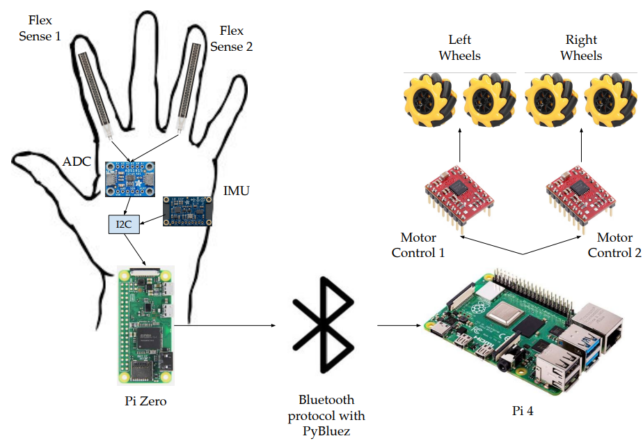
General Hardware Diagram
The general hardware diagram is highlighted in the figure above. The design contained two main parts, the glove and the robot. The glove was responsible for collecting all the movement data from the user, and sending it over to the pi for usage via PyBluez - a bluetooth protocol library that is highlighted in the software section below. From there, the Pi 4 parsed the bluetooth packets and used them to control how the omni-directional wheels rotated. Below is a diagram that was useful when implementing the wheels.
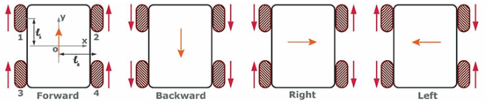
Omni-Directional Wheel Movement [2]
While testing the spinning of the motor wheels, we noticed that one of the motors only spun in one direction. Because the software was abstracted, and the other wheels worked properly, we realized that this was most likely a hardware bug. In attempt to solve the issue, we tried a new DC motor, swapping the motor drivers, and even trying a new breadboard in case of an internal short. We soon realized that the same thing was still happening, which meant that it had something to do with one of the direction pins. We scoped the outputs of the two direction pins and realized that GPIO 25 was always at a 3.3V high, even when we told it to go low. We concluded that this GPIO pin was used by the PiTFT, which always had the pin at a 3.3V high. Thus, we swapped the GPIO pin and everything worked as intended, and the wheels were able to be moved as in the chart above. This took a lot of time to debug, and could have easily been avoided if we used the oscilliscope first. The GPIO pins that worked in the end were 4, 5, 6, 12, 13, 16, 19, 20, 21, 23, 24, and 26. This is a total of 12 pins needed, because each individual motor required two pins for direction and one in for a PWM signal. Note that pin 23 is used by the PiTFT for one of the buttons. We just avoided using the buttons, and everything worked as intended.
In order to get valuable data from the flex sensors, we needed to read the voltage through a voltage divider. Since the flex sensor is basically just a variable resistor on a range from 20 kohms to 70 kohms, we figured that using a 1 kohm resistor would work when dividing an input voltage of 3.3V. This was more than safe enough for the ADC. Below, we see a diagram of how this was wired to the ADC. Note that the wiring for the IMU was trivial, and just required connection to power and the I2C line
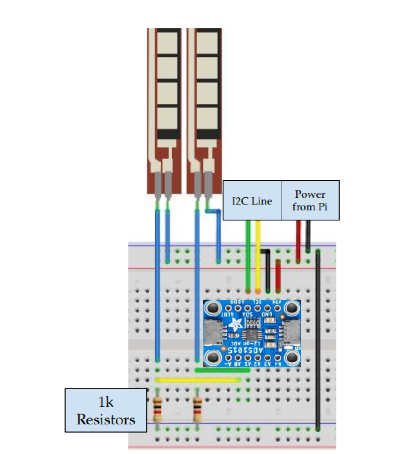
Flex Sensor Voltage Divider
Hardware Testing
The hardware testing was easy to blackbox test. It mostly came in the form of observing physical behavior of the robot to insure that it could support the software. For example, observing the behavior of the motors to ensure that they spun in the correct orientation. As highlighted above, one of the large hardware issues that we ran into was a directional pin that was constantly high, even when told to output a low signal. This was ultimately debugged with the oscilliscope. See above for more information. One of the aspects that worked smoothly at the beginning of the project was implementing the hardware for the flex sensors. After wiring to the ADC, we were successfully able to read the data to a monitor and detect when the flex sensors were flexed. Implementing this went smoothly without errors, but as we integrated the system onto the glove, we noticed that the flex sensors got kinked. This added resistance to the flex sensor, which was harmful to the glove.py code, as it was reading slight bends in the fingers as a grab. This was hard to foresee, and happened during the demo. As a quick temporary fix, we could decrease the threshold value for a grab in glove.py but this would only work for a few minutes, until the flex sensor got more kinked by the bending of the fingers. In the future, to avoid this issue, we would consider placing the flex sensors on top of the finger instead of the botttom to avoid the compression that the flex sensor undergoes when getting crunched by the fingers. This could alternatively be fixed with a software controlled threshold.
Software Design
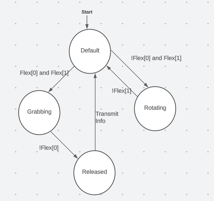
Software State Diagram
The Software comprises two main programs running simultaneously on the Pi 4 and the Pi 0. Two programs make use of the Raspberry Pi PyBluez library to facilitate bluetooth communications between the two embedded systems. Within each Bluetooth packet we encode information such as whether or not the glove is currently grabbing, rotating, or releasing the robot, as well as a vector corresponding to the direction that the robot should either rotate or translate. On the Pi 0, we poll both sensors using the I2C bus. The ADC connected to the flex sensors is one of our I2C devices and the IMU is the other. We were ableto install two I2C libraries for each of the devices to implement this. glove.py operates on an underlying FSM that we control using a couple of boolean flags in the code. The default state is a non-transmission state, meaning we do not transmit any information to the bot when we are in this state. If the glove is not currently grabbing or rotating, or did not just release the robot, then we are in the default state. If we are in the default state and then the ring finger flex sensor is flexed, we transition into the rotation state, during which we transmit accelerometer data in the x-direction to the Pi 4. This is because we noticed that the accelerometer is sensitive to gravity, so rotating it along the x-axis provides reliable data to encode rotation. Releasing the ring finger flex sensor returns the system to the default state. If we are in the default state and we flex both sensors beyond a certain threshold, then we transition to the grabbing state, where we do not encode any relevant vector information in the packet. If the Pi 4 receives a "grabbing" communication, it simply knows to stop the motors in their place, which emulates our catching function. Lastly, if we are in the grabbing state and we release the flex sensors, we enter the released state, where we then determine the direction of the throw via the gyroscope and transmit this direction in the bluetooth packet via the gyroscope vector.
Development for the software described above took a lot of trial and error. For the most part, utilizing the libraries was pretty straightforward due to the facility of Linux. We simply connected to the internet and used pip to install the relevant libraries. Bluetooth communications took some debugging to achieve, but we eventually discovered that the only relevant information that the Pi 0 needed to know to establish a connection with the Pi 4 was the Pi 4's MAC ID number. The most difficult part of the Project to work with was the IMU on account of its noise. We wanted to utilize the accelerometer to determine the direction of the throw but after much trial and error and after attempting a couple of filters, we decided that the time commitment to implement a proper Kalman Filter to the accelerometer data was not worth it considering that the gyroscope produced consistent, stable readings. Thus the throwing motion changed from a translational movement of the arm to a flick of the wrist. The flex sensors also proved rather unreliable. Their continued use would increase their default resistance, so we would have to continually adjust the thresholds we set in the code to account for this. A potential improvement for this could be to automate the calculation of the grabbing thresholds by sampling the flex sensors at the program's beginning then setting the thresholds to a suitable percentage of the default resistance.
Software Testing
We unit tested our software using Test Driven Development as we wrote up our scripts. Each time we added a new sensor, we wrote up a test script for said sensor to get an understanding of how the sensor worked and what kind of readings we were receiving. We also had a bluetooth script running on the Pi 4 that would constantly loop and display packets of information received from the Pi 0. This enabled us to experiment around with every feature before we integrated it into the main script.
Results
Not everything in our project went according to plan. For one thing, we encountered a lot more issues with the IMU than we anticipated. In the beginning, we expected to use the accelerometer predominantly to determine the direction of the throw, but when this proved unintuitive and overcomplicated, we transitioned to the gyroscope. In addition, we did not integrate another glove to the system. We wanted to stay around a budget of $100 and adding more flex sensors on top of another ADC to the system would accrue additional expenses. If we were to have tried to create another glove, we likely would have used a Pico for affordability. Lastly, our system experienced a lot more wear and tear than we would have liked. The more we used the glove, the more the flex sensors would deterioriate, throwing off our code.
Conclusion
In the end, we were able to manipulate the ground control robot along two axes on top of controlling its rotation using a set of omnidirectional wheels whose outputs were controlled by the Pi 4 receiving data from the glove. To improve scalability, we think it is imperative to address the issues with the flex sensors. Having some sort of aforementioned software control to calculate the initial default resistance of the flex sensors could prove incredibly beneficial as this could automate the process of determining a proper threshold to set for the "grabbing" and "rotating" inputs. In addition, making use of a Kalman Filter could alleviate the IMU noise issues we were experiencing. Since we had to compromise and change the physical motion of the glove to control the robot, a filter could enable both the use of the accelerometer and the ability to see through our original vision for the project. While we were able to implement the "Force Grab" and "Force Throw", it would have been cool to have the robot track along a path determined by the motion of our arm.
Work Distribution
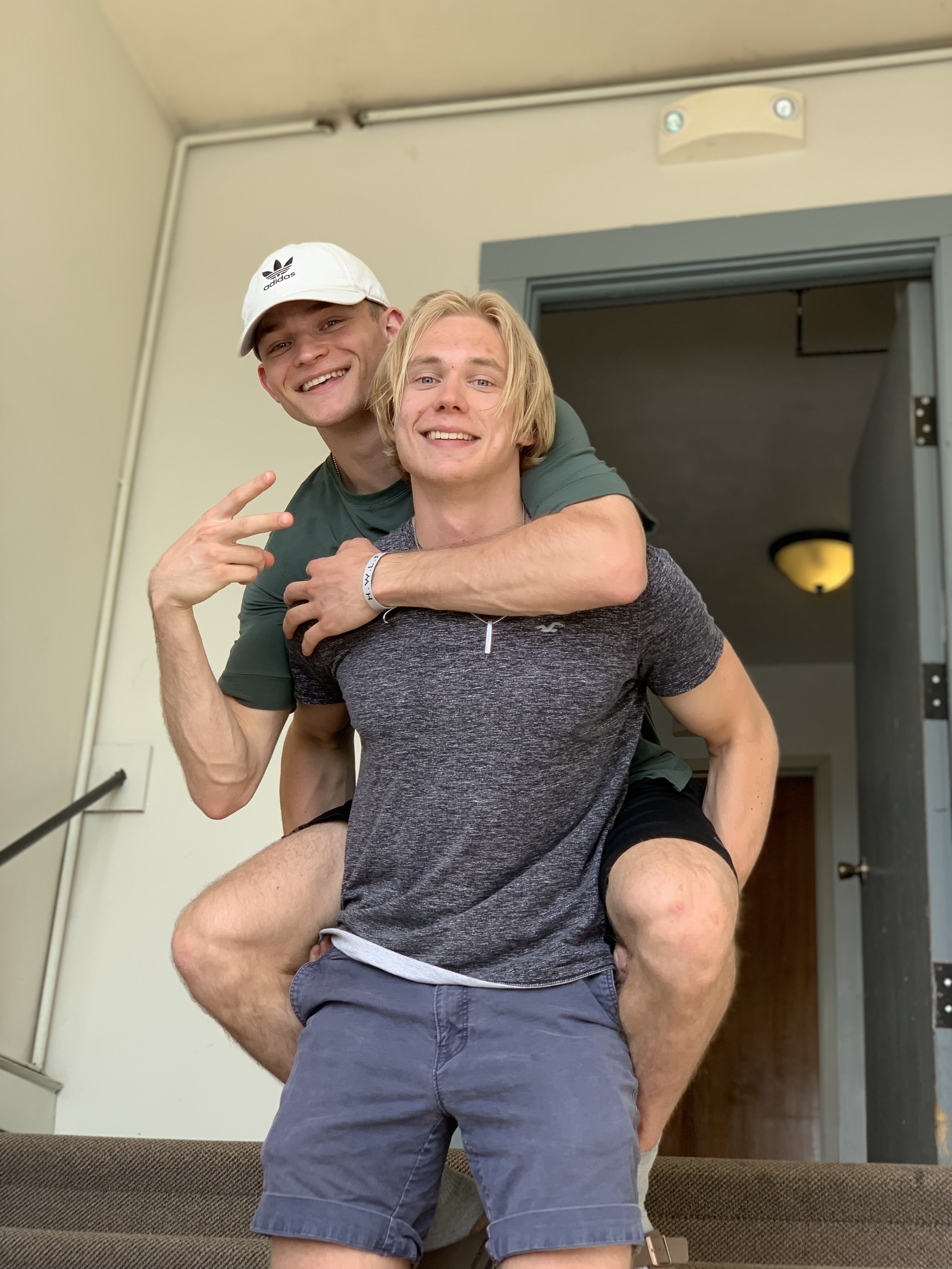
Jonas Funk (left) & Antti Meriluoto (right)
Jonas
jwf224@cornell.edu
Researched and bought required components
Designed and implemented hardware design, including soldering and breadboarding
Helped debug python scripts

Antti
ahm234@cornell.edu
I wrote the bot.py and glove.py scripts as well as all of the additional scripts we used to debug the flex sensors, the IMU, and Bluetooth Communications.
Parts List
- Raspberry Pi $35.00
- 12-Bit ADC $12
- 2 flex sensors $16
- Omni-Directional Wheels $20
- 2 motor controllers - Provided in lab
- Pi Zero - Provided in lab
- IMU - Provided in lab
- Resistors and Wires - Provided in lab
Total: $69.95
References
[1]DAWN Avatar Robots[2]Omni-Direcstional Wheel Movement
[3]IMU I2C Library
[4]ADC Library
[5]PyBluez
Code Appendix
#!/usr/bin/python3
'''
bot.py
Antti Meriluoto and Jonas Funk

Script running on the Pi 4 that controls the 4 omni-directional wheels
on the ground bot.
'''

import sys
import time
import RPi.GPIO as GPIO
import pygame
import bluetooth

server_socket = bluetooth.BluetoothSocket(bluetooth.RFCOMM)
port = 1
server_socket.bind(("", 1))

# Listen for incoming Bluetooth connections
server_socket.listen(1)

# Get the port number assigned to the socket
port = server_socket.getsockname()[1]

# Print the port number to the console
print("Waiting for connection on RFCOMM channel", port)

# Accept an incoming Bluetooth connection
client_socket, client_info = server_socket.accept()
print("Accepted connection from", client_info)

frequency = 50
GPIO.setmode(GPIO.BCM)

class Motor:
    '''
    Instance of class Motor represents one of four motors connected to our
    '''
    def __init__(self, dir1, dir2, pwm):
        self.dir1 = dir1
        self.dir2 = dir2
        self.pwm_pin = pwm
        GPIO.setup(self.pwm_pin, GPIO.OUT)
        self.pwm = GPIO.PWM(self.pwm_pin, frequency)

    '''
    Setup the GPIO for the motor
    '''
    def setup(self):
        GPIO.setup(self.dir1, GPIO.OUT)
        GPIO.setup(self.dir2, GPIO.OUT)

    '''
    Rotate Clockwise
    '''
    def clockwise(self, dc):
        GPIO.output(self.dir1, GPIO.HIGH)
        GPIO.output(self.dir2, GPIO.LOW)
        self.pwm.start(dc)
    '''
    Rotate Counterclockwise
    '''
    def counterclockwise(self, dc):
        GPIO.output(self.dir1, GPIO.LOW)
        GPIO.output(self.dir2, GPIO.HIGH)
        self.pwm.start(dc)
    '''
    Stop the motor
    '''
    def stop(self):
        self.pwm.stop()

frontRightMotor = Motor(16, 12, 24)
frontLeftMotor = Motor(19, 26, 23)

backRightMotor = Motor(4, 20, 21)
backLeftMotor = Motor(5, 6, 13)

frontRightMotor.setup()
frontLeftMotor.setup()
backRightMotor.setup()
backLeftMotor.setup()


'''
These functions define how to manipulate the robot
'''

def rotateRight():
    frontLeftMotor.counterclockwise(50)
    backLeftMotor.counterclockwise(50)
    frontRightMotor.clockwise(50)
    backRightMotor.clockwise(50)

def rotateLeft():
    frontLeftMotor.clockwise(50)
    backLeftMotor.clockwise(50)
    frontRightMotor.counterclockwise(50)
    backRightMotor.counterclockwise(50)

def goForward(y_dc):
    frontRightMotor.counterclockwise(y_dc)
    frontLeftMotor.counterclockwise(y_dc)
    backRightMotor.counterclockwise(y_dc)
    backLeftMotor.counterclockwise(y_dc)

def goBackward(y_dc):
    frontRightMotor.clockwise(y_dc)
    frontLeftMotor.clockwise(y_dc)
    backRightMotor.clockwise(y_dc)
    backLeftMotor.clockwise(y_dc)

def goRight(x_dc):
    frontRightMotor.counterclockwise(x_dc)
    frontLeftMotor.counterclockwise(x_dc)
    backLeftMotor.clockwise(x_dc)
    backRightMotor.clockwise(x_dc)

def goLeft(x_dc):
    frontRightMotor.clockwise(x_dc)
    frontLeftMotor.clockwise(x_dc)
    backLeftMotor.counterclockwise(x_dc)
    backRightMotor.counterclockwise(x_dc)

def stopMotors():
    frontLeftMotor.stop()
    frontRightMotor.stop()
    backLeftMotor.stop()
    backRightMotor.stop()


i = 0
direction = "NORTH"
while True:
    try:
        #Receive a bluetooth packet
        data = client_socket.recv(1024)
        if not data:
            break
        data = str(data)
        print(data)

        #Parse the data received via bluetooth
        data = data.replace("b'", "", 1)
        parsed = data.split(",")
        prev = parsed[3]
        parsed[3] = parsed[3].replace("True", "", 1)
        if parsed[3] == prev:
            parsed[3] = parsed[3].replace("False", "", 1)
        parsed[3] = parsed[3].replace("'", "", 1)
        print(parsed)

        #If we're grabbing the robot
        if parsed[0] == "False" and parsed[1] == "False":
            stopMotors()
        elif parsed[0] == "True": #If we're rotating the robot
            print("rotating")
            rotation = float(parsed[2])
            if rotation > 3:
                rotateLeft()
                time.sleep(0.2)
                stopMotors()
            if rotation < -3:
                rotateRight()
                time.sleep(0.2)
                stopMotors()
        elif parsed[1] == "True": #If we've thrown the robot
            x, z = float(parsed[2]), float(parsed[3])
            if abs(x) > abs(z):
                direction = "NORTH"
            else:
                direction = "EAST"
            if direction == "NORTH" and x > 0:
                goBackward(75)
            elif direction == "NORTH" and x < 0:
                goForward(75)
            elif direction == "EAST" and z < 0:
                goRight(100)
            elif direction == "EAST" and z > 0:
                goLeft(100)
    except bluetooth.btcommon.BluetoothError as error:
        print("Bluetooth connection error:", error)
        break


GPIO.cleanup()
'''
glove.py
Antti Meriluoto and Jonas Funk

Script running on the Pi 0 that polls the flex sensors and the IMU to transmit
control packets to the Pi 4.
'''

from mpu6050 import mpu6050
import time
import bluetooth

import Adafruit_ADS1x15

server_address = "dc:a6:32:b4:13:d4"
client_socket = bluetooth.BluetoothSocket(bluetooth.RFCOMM)
client_socket.connect((server_address,1))

sensor = mpu6050(0x68)
adc = Adafruit_ADS1x15.ADS1115()


start = time.time()

x_sum = 0
y_sum = 0
z_sum = 0
now = start
count = 0
correction_acceleration = 0.5
grabbing = False
rotating = False
release = False
x_peak, z_peak = False, False
x_gyro, y_gyro, z_gyro = 0, 0, 0

x_sum, z_sum = 0,0 #We sum up the absolute value of these features to determine
# where the angular velocity experienced the greatest change and thus what axis we're throwing alongside
x_data, z_data = 0,0
flex = [0] * 2
x_accel = 0
while True:
    rotating, release = False, False

    flex[0], flex[1] = adc.read_adc(0, gain = 1), adc.read_adc(1, gain = 1)
    print(flex)

    gyro  = sensor.get_gyro_data()
    accel = sensor.get_accel_data()
    if flex[0] < 1200 and flex[1] < 2500: #If we're grabbing the robot
        #Transition to the grabbing state
        if gyro["x"] > 150 or gyro["x"] < -150 and not x_peak: #If we haven't yet hit the threshold that we have defined to determine direction
            x_gyro = gyro["x"]
            x_sum += abs(gyro["x"])
            x_peak = True
        if gyro["z"] > 150 or gyro["z"] < -150 and not z_peak:
            z_gyro = gyro["z"]
            z_sum += abs(gyro["z"])
            z_peak = True
        grabbing = True
    elif grabbing: #If we just finished grabbing the robot and have since released it
        #Transition to the Released State
        x_peak, z_peak = False, False
        print("X: " + str(x_gyro))
        print("Z: " + str(z_gyro))
        time.sleep(0.2)
        grabbing = False
        release = True
    elif flex[1] < 2200: #If we're rotating
        #Transition to the Rotating State
        time.sleep(0.05)
        if flex[0] > 1700 and flex[1] < 2200:
            print("Rotate")
            rotating = True
            x_accel = accel["x"]
            grabbing = False

    if rotating:
        x_data = x_accel
        z_data = 0
    elif x_sum > z_sum:
        x_data = x_gyro
    else:
        x_data = 0
        z_data = z_gyro
    packet = str(rotating) + "," + str(release) + "," + str(x_data) + \
        "," + str(z_data)

    if(rotating or release or grabbing):
        client_socket.send(packet)
        if not grabbing:
            x_accel, y_accel = 0,0
            x_gyro, z_gyro = 0,0
            x_sum, z_sum = 0,0
            time.sleep(0.1)